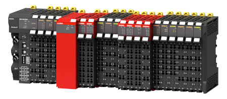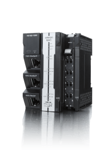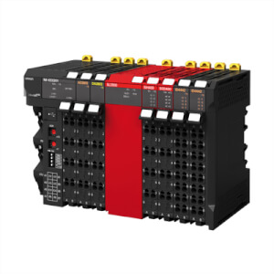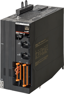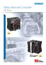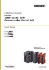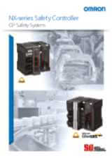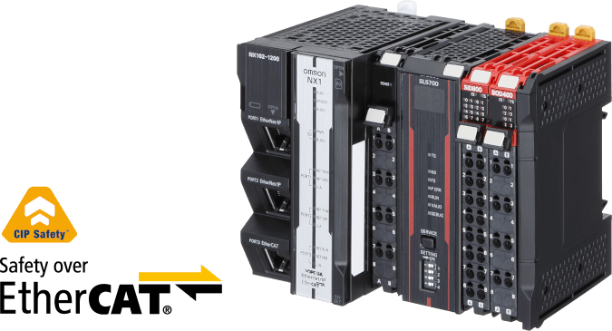
NX Safety Hybrid
Dalla singola macchina all'intera linea di produzione, sicurezza interconnessa
È estremamente rapido, semplice e flessibile integrare la sicurezza nelle linee di produzione combinando due diverse reti integrate, Ethernet/IP (Common Industrial Protocol Safety (CIP-S)) e EtherCAT (Safety over EtherCAT (FSoE))
- 1 porta EnerNet/IP integrata (100Base-TX)
- 1 porta CIP-Safety su EtherNet/IP (max 16 CIP-Safety comunicazione)
- 1 porta master FSoE integrata su EtherCAT (max 64 nodi)
- Fino a 254 connessioni di sicurezza con NX-SL5700
- Fino a 32 moduli di I/O NX locali
- Indirizzamento multi-cast possibile
- Fino a 12 assi (8 assi con movimento sincronizzato e 4 assi PTP)
Caratteristiche ed info per ordinare
Ordering Information
NX1 series CPU units
| CPU | Appearance | Program capacity | Variables capacity | Number of axes | Functionalities | Order code | |||||
|---|---|---|---|---|---|---|---|---|---|---|---|
| Real axes | Motion control servo axes | Single-axis position control axes | Sequence | OPC UA | Motion | DB connection | |||||
| NX102 |  |
5 MB |
1.5 MB: Retained 32 MB: Not retained |
12 axes | 8 axes | 4 axes | NX102-1220 | ||||
| – |
NX102-1200 | ||||||||||
| 8 axes | 4 axes | NX102-1120 | |||||||||
| – | NX102-1100 | ||||||||||
| 6 axes | 2 axes | NX102-1020 | |||||||||
| – | NX102-1000 | ||||||||||
| 4 axes | 0 axes | – | NX102-9020 | ||||||||
| – | – | NX102-9000 | |||||||||
The end cover unit NX-END02 is included with the CPU unit.
NX-series Safety Control Units
Safety CPU Units
| Unit type | Appearance | Specifications | Unit version | Order code | |||
|---|---|---|---|---|---|---|---|
| Maximum number of safety I/O points | Program capacity | Number of safety I/O connections | I/O refreshing method | ||||
| Safety CPU Unit (NX-SL5 |
 |
1024 points | 2048 KB | 128 | Free-Run refreshing | Ver. 1.3 | NX-SL5500 |
 |
2032 points | 4096 KB | 254 | NX-SL5700 | |||
Refer to your local OMRON website for
details of the NX-SL5
Safety Input Units
| Unit type | Appearance | Specifications | Unit version | Order code | ||||||
|---|---|---|---|---|---|---|---|---|---|---|
| Number of safety input points | Number of test output points | Internal I/O common | Rated input voltage | OMRON special safety input devices | Number of safety slave connections | I/O refreshing method | ||||
| Safety Input Units |  |
4 points | 2 points | Sinking inputs (PNP) | 24 VDC | Cannot be connected.
2
Various OMRON special safety input devices can be connected directly without a special controller. For detail of connectable OMRON special safety input devices, refer to NX-series User's Manual Safety Control Unit/Communication Control Unit (Cat. No. Z395). |
1 | Free-Run refreshing | Ver. 1.1 | NX-SIH400 |
 |
8 points | Cannot be connected. |
Ver. 1.0 | NX-SID800 | ||||||
Safety Output Units
| Unit type | Appearance | Specifications | Unit version | Order code | |||||
|---|---|---|---|---|---|---|---|---|---|
| Number of safety output points |
Internal I/O common |
Maximum load current | Rated voltage |
Number of safety slave connections |
I/O refreshing method |
||||
| Safety Output Units |  |
2 points | Sourcing outputs (PNP) |
2.0 A/point, 4.0 A/Unit at 40°C, and 2.5 A/Unit at 55°C The maximum load current depends on the installation orientation and ambient temperature. |
24 VDC | 1 | Free-Run refreshing | Ver. 1.0 | NX-SOH200 |
 |
4 points | 0.5 A/point and 2.0 A/Unit | NX-SOD400 | ||||||
NX-series Standard I/O units
For the selection of standard I/O units please refer to the NX Series product website (https://industrial.omron.eu/en/products/nx-series).
Automation Software Sysmac Studio
Please purchase a DVD and required number of licenses the first time you purchase the Sysmac Studio. DVDs and licenses are available individually. Each model of licenses does not include any DVD.
| Product name | Specifications | Number of licenses | Media | Order code |
|---|---|---|---|---|
| Sysmac Studio Safety Edition Ver. 1.
2
The Safety Edition can be used with the Communication Control Unit and EtherNet/IP Coupler Unit. |
Sysmac Studio Safety Edition is a license including necessary setting functions for the safety control system. Note:This
product is a license only. You need the Sysmac Studio Standard Edition
DVD media to install it.
|
1 license | – | SYSMAC-FE001L |
| Sysmac Studio Standard Edition Ver. 1.
2
The Sysmac Studio Standard Edition License (SYSMAC-SE2 |
The Sysmac Studio is the software that provides an integrated environment for setting, programming, debugging and maintenance of machine automation controllers including the NJ/NX-series CPU Units, NY-series Industrial PC, EtherCAT Slave, and the HMI. Sysmac Studio runs on the following OS. Windows 7(32-bit/64-bit version)/8(32-bit/64-bit version)/8.1(32-bit/64-bit version)/10(32-bit/64-bit version) |
– (Media only) | DVD | SYSMAC-SE200D |
For details of the Automation Software Sysmac Studio, refer to your local OMRON website.
Optional Products
| Product name | Specifications | Order code |
|---|---|---|
| Memory Card | SD memory card, 2 GB | HMC-SD291 |
| SD memory card, 4 GB | HMC-SD491 | |
| Unit/Terminal Block Coding Pins | For 10 Units (Terminal Block: 30 pins, Unit: 30 pins) | NX-AUX02 |
| Product name | Specifications | Order code | |||
|---|---|---|---|---|---|
| No. of terminals | Terminal number indications | Ground terminal mark | Terminal current capacity | ||
| Terminal Block | 8 | A/B | Provided | 10 A | NX-TBC082 |
| 8 | A/B | None | 10 A | NX-TBA082 | |
| 16 | A/B | None | 10 A | NX-TBA162 | |
Accessories
Communication Control Unit Accessories
| Product name | Remark | Order code |
|---|---|---|
| End Cover | One End Cover is provided with the Communication Control Unit. | NX-END02 |
Specifications
Regulations and Standards
NX-series Safety Control Units
| Certification body | Standards | |
|---|---|---|
| TÜV Rheinland
2
The FSoE protocol was certified for applications in which OMRON FSoE devices are connected to each other. For compatibility with FSoE devices other than OMRON FSoE devices, the customer must validate FSoE communications. |
EN ISO 13849-1EN ISO 13849-2IEC 61508 parts 1-7IEC/EN 62061IEC/EN 61131-2 | IEC 61326-3-1IEC 61131-6
2
Only
NX-SL5500/5700 have obtained IEC 61131-6 and FSPC certifications. |
| UL | NRAQ (UL61010-1, and UL 61010-2-201)NRAG
(ANSI/ISA 12.12.01, or UL 121201)NRAQ7 (CSA C22.2 No. 61010-1, and
CSA C22.2 No. 61010-2-201)FSPC (IEC 61508 and ISO 13849)
2
Only
NX-SL5500/5700 have obtained IEC 61131-6 and FSPC certifications. |
|
- Requirements for SIL 3 (Safety Integrity Level 3) in IEC 61508, IEC/EN 62061, (Functional Safety of Electrical/Electronic/Programmable Electronic Safety-related Systems)
- Requirements for PLe (Performance Level e) and for safety category 4 in EN ISO13849-1
The NX-series Safety Control Units are also registered for RCM, EAC, and KC compliance.
General Specifications
| Item | Specifications | |
|---|---|---|
| Enclosure | Mounted in a panel (open) | |
| Grounding method | Ground to 100 Ω or less | |
| Operating environment |
Ambient operating temperature | 0 to 55°C |
| Ambient operating humidity | 10% to 95% (with no condensation or icing) | |
| Atmosphere | Must be free from corrosive gases. | |
| Ambient storage temperature | −25 to 70°C (with no condensation or icing) | |
| Altitude | 2,000 m max. | |
| Pollution degree | 2 or less: Conforms to JIS B3502 and IEC 61131-2. | |
| Noise immunity | Conforms to IEC 61131-2. 2 kV on power supply line |
|
| Insulation class | Class III (SELV) | |
| Overvoltage category | Category II: Conforms to JIS B3502 and IEC 61131-2. | |
| EMC immunity level | Zone B | |
| Vibration resistance | Conforms to IEC 60068-2-6. 5 to 8.4 Hz with 3.5-mm amplitude 8.4 to 150 Hz, acceleration of 9.8 m/s2 100 minutes each in X, Y, and Z directions (10 sweeps of 10 min each = 100 min total) |
|
| Shock resistance | Conforms to IEC 60068-2-27. 147 m/s2, 3 times each in X, Y, and Z directions |
|
| Insulation resistance
2
The specifications are for the Safety Input
Unit, and Safety Output Unit, not for the Safety CPU Unit. |
20 MΩ between isolated circuits (at 100 VDC) | |
| Dielectric strength
2
The specifications are for the Safety Input
Unit, and Safety Output Unit, not for the Safety CPU Unit. |
510 VAC for 1 min between isolated circuits, leakage current: 5 mA max. | |
| Installation method | DIN Track (IEC 60715 TH35-7.5/TH35-15) | |
Safety Control Units
Safety CPU Units NX-SL5500/SL5700
| Unit name | Safety CPU Unit | |
|---|---|---|
| Model | NX-SL5500 | NX-SL5700 |
| Maximum number of safety I/O points | 1024 points | 2032 points |
| Program capacity | 2048 KB | 4096 KB |
| Number of safety master connections
2
This
is the maximum number of Safety I/O connections that can be set
to this Unit. The value is the total number of CIP Safety originator
connections, CIP Safety target connections, and FSoE master connections. |
128 | 254 |
| Number of CIP Safety originator connections | 128 | 254 |
| Number of CIP Safety target connections | 4 | 4 |
| Number of originators that can be connected with a multi-cast connection |
8 | 8 |
| Number of FSoE master connections | 128 | 254 |
| I/O refreshing method | Free-Run refreshing | |
| External connection terminals | None | |
| Indicators | [TS] indicator, [NS] indicator, [FS] indicator, [P ERR] indicator, [RUN] indicator, [VALID] indicator, [DEBUG] indicator, seven-segment indicator 
|
[TS] indicator, [NS] indicator, [FS] indicator, [P ERR] indicator, [RUN] indicator, [VALID] indicator, [DEBUG] indicator, seven-segment indicator 
|
| Hardware switch settings | [SERVICE] switch, [SETTING] switch
|
[SERVICE] switch, [SETTING] switch
|
| Dimensions | 30 × 100 × 71 mm (W × H × D) | |
| I/O power supply method | Not supplied. | |
| Current capacity of I/O power supply terminals | No I/O power supply terminals | |
| NX Unit power consumption | 3.35 W max.
2
The cable length
for the Units (Communication Control Unit and Power Supply Unit
for NX Units) that supply power to the corresponding Unit must be
up to 20 m. |
|
| Current consumption from I/O power supply | No consumption | |
| Weight | 130 g max. | |
| Installation orientation and restrictions |
Installation orientation: Upright installation Restriction
2 : None.
Only NX102 CPU Units and Communication
Control Units can be connected. NX1P2 CPU Units or Communications
Coupler Units cannot be connected. |
|
Safety Input Units NX-SIH400/SID800
| Unit name | Safety Input Unit | |
|---|---|---|
| Model | NX-SIH400 | NX-SID800 |
| Number of safety input points | 4 points | 8 points |
| Number of test output points | 2 points | 2 points |
| Internal I/O common | PNP (sinking inputs) | |
| Rated input voltage | 24 VDC (20.4 to 28.8 VDC) | |
| OMRON special safety input devices |
Can be connected. | Cannot be connected. |
| Number of safety slave connections |
1 | |
| I/O refreshing method | Free-Run refreshing | |
| External connection terminals | Screwless clamping terminal block (8 terminals) | Screwless clamping terminal block (16 terminals) |
| Indicators | [TS] indicator, [FS] indicator, [IN] indicator,
[IN ERR] indicator
|
[TS] indicator, [FS] indicator, [IN] indicator,
[IN ERR] indicator
|
| Safety input current | 4.5 mA TYP. | 3.0 mA TYP. |
| Safety input ON voltage | 11 VDC min. | 15 VDC min. |
| Safety input OFF voltage/OFF current |
5 VDC max., 1 mA max. | |
| Test output type | Sourcing outputs (PNP) | |
| Test output load current | 25 mA max. | 50 mA max. |
| Test output residual voltage | 1.2 V max. (Between IOV and all output terminals) | |
| Test output leakage current | 0.1 mA max. | |
| Dimensions | 12 × 100 × 71 mm (W × H × D) | |
| Isolation method | Photocoupler isolation | |
| Insulation resistance | 20 MΩ min. between isolated circuits (at 100 VDC) | |
| Dielectric strength | 510 VAC for 1 min between isolated circuits, leakage current: 5 mA max. | |
| I/O power supply method | Power supplied from the NX bus | |
| Current capacity of I/O power supply terminals |
No applicable terminals. | |
| NX Unit power consumption | Connected to a CPU Unit or a Communication Control Unit 1.10 W max.Connected to a Communications Coupler Unit 0.70 W max. | Connected to a CPU Unit or a Communication Control Unit 1.10 W max.Connected to a Communications Coupler Unit 0.75 W max. |
| Current consumption from I/O power supply |
20 mA max. | |
| Weight | 70 g max. | |
| Circuit layout |  |
 |
| Terminal connection diagram | Si0 to Si3: Safety input terminals T0 and T1: Test output terminals  Refer to User's manual (Cat. No. Z395) for details. |
Si0 to Si7: Safety input terminals T0 and T1: Test output terminals  Refer to User's manual (Cat. No. Z395) for details. |
| Installation orientation and restrictions |
Installation orientation:
Restrictions: Maximum ambient temperature is 50°C for any orientation other than upright installation. |
|
| Protective functions | Overvoltage protection circuit and short detection (test outputs) | |
Safety Output Units NX-SOH200/SOD400
| Unit name | Safety Output Unit | |
|---|---|---|
| Model | NX- SOH200 | NX- SOD400 |
| Number of safety output points | 2 points | 4 points |
| Internal I/O common | PNP (sourcing outputs) | |
| Maximum load current | 2.0 A/point 4.0 A/Unit at 40°C 2.5 A/Unit at 55°CThe maximum load current depends on the installation orientation and ambient temperature |
0.5 A/point and 2.0 A/Unit |
| Rated voltage | 24 VDC (20.4 to 28.8 VDC) | |
| Number of safety slave connections |
1 | |
| I/O refreshing method | Free-Run refreshing | |
| External connection terminals | Screwless clamping terminal block (8 terminals) | |
| Indicators | [TS] indicator, [FS] indicator, [OUT] indicator, [OUT ERR] indicator 
|
[TS] indicator, [FS] indicator, [OUT] indicator, [OUT ERR] indicator 
|
| Safety output ON residual voltage | 1.2 V max. (Between IOV and all output terminals) | |
| Safety output OFF residual voltage | 2 V max. (Between IOG and all output terminals) | |
| Safety output leakage current | 0.1 mA max. | |
| Dimensions | 12 × 100 × 71 mm (W × H × D) | |
| Isolation method | Photocoupler isolation | |
| Insulation resistance | 20 MΩ min. between isolated circuits (at 100 VDC) | |
| Dielectric strength | 510 VAC for 1 min between isolated circuits, leakage current: 5 mA max. | |
| I/O power supply method | Power supplied from the NX bus | |
| Current capacity of I/O power supply terminals |
IOG: 2 A max./terminal | IOG (A3 and B3): 2 A max./terminal IOG (A7 and B7): 0.5 A max./terminal |
| NX Unit power consumption |
|
|
| Current consumption from I/O power supply |
40 mA max. | 60 mA max. |
| Weight | 65 g max. | |
| Circuit layout |  |
 |
| Terminal connection diagram | So0 and So1: Safety output terminals IOG: I/O power supply 0 V  Refer to User's manual (Cat. No. Z395) for details. |
So0 to So3: Safety output terminals IOG: I/O power supply 0 V  Refer to User's manual (Cat. No. Z395) for details. |
| Installation orientation and restrictions |
Installation orientation:
For upright installation, the ambient temperature is restricted as shown below depending on the total Unit load current.  For all installation orientations other than upright installation, the ambient temperature is restricted as shown below according to the total Unit load current. 
|
Installation orientation:
Restrictions: |
| Protective functions | Overvoltage protection circuit and short detection (test outputs) | |
Come possiamo aiutarti?
Se hai domande o desideri richiedere un preventivo, contattaci o inviaci una richiesta.
Contattaci NX Safety Hybrid
Grazie per averci sottoposto la vostra richiesta. Vi risponderemo non appena possibile.
Purtroppo abbiamo problemi tecnici. Il tuo modulo non è stato ricevuto correttamente. Ci scusiamo per l'inconveniete e ti chiediamo per favore di riprovare più tardi.
DownloadPreventivo per NX Safety Hybrid
Tramite questo modulo può richiedere un'offerta relativa al prodotto prescelto. Completi, per favore, i campi contrassegnati con *. I suoi dati personali verranno trattati secondo le normative vigenti. Le ricordo che il minimo importo fatturabile è di 400 € a cui bisogna aggiungere 25 € di spese amministrative.

Grazie per averci richiesto un'offerta. Vi risponderemo non appena possibile.
Purtroppo abbiamo problemi tecnici. Il tuo modulo non è stato ricevuto correttamente. Ci scusiamo per l'inconveniete e ti chiediamo per favore di riprovare più tardi.
DownloadVideo

-

Omron NX-Series Safety Network Controller
NX Series CIP Safety Controller with EtherCAT and Ethernet/IP capabilities. In addition to new hardware, Sysmac Studio new functions include Automatic Programming, Safety Data Logging, and Online Functional Test. For more information visit: USA Canada Mexico
03:22
