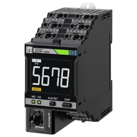
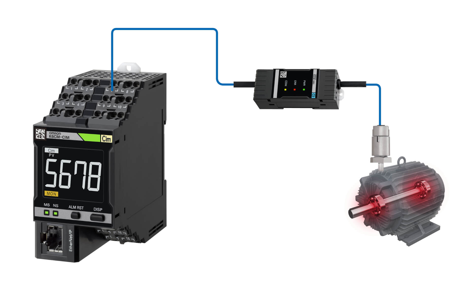
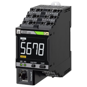
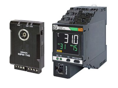
K6CM-VBM
Dispositif de surveillance de l'état du moteur : surveillance des vibrations
Le contrôleur K6CM-VBM analyse les vibrations détectées sur les moteurs électriques pour surveiller l'état de la transmission du moteur entier. Vous pouvez ainsi effectuer une maintenance avant que des problèmes graves ne se produisent, et ainsi éviter une intervention non planifiée et des temps d'arrêt coûteux.
Avantages de cette technologie :
- Détection ultra-efficace des dommages liés au roulement du moteur, grâce à l'analyse du domaine de temps et de fréquence
- Configuration facile sur les machines à champ vert et à champ marron, grâce à une interface logicielle conviviale permettant de régler l'appareil en quelques minutes
- Possibilité de détecter des anomalies telles que le déséquilibre de charge, les courroies mal alignées, les problèmes de rotor et de stator
- notifications en cas d'avertissement/d'alarme,
- surveillance à distance
- Interaction avec les applications personnalisées et le serveur MQTT.
Caractéristiques et références
| Produit | Supply voltage AC | Supply voltage DC | Description | |
|---|---|---|---|---|
|
|
100-240 V | Motor Condition Monitoring, AC, 3-phase, Induction motor, Vibration & temperature model, 100 to 240 VAC, Transistor control output, Push-in Plus, LCD display, Ethernet IP |
|
|
|
|
20.4-26.4 V | 20.4-26.4 V | Motorzustandsüberwachung, AC, 3-Phasen, Induktionsmotor, Modell für Vibrationen und Temperatur, 24 VAC/VDC, Transistorsteuerausgang, Push-in Plus, LCD-Display, Ethernet IP |
|
Besoin d'aide ?
Nous sommes là pour vous aider ! Contactez-nous et nos spécialistes vous aideront à trouver la meilleure solution pour votre entreprise.
Contactez-moi K6CM-VBM
Merci de votre demande. Nous reviendrons vers vous dès que possible.
Nous rencontrons des problèmes techniques. Votre demande ne peut être traitée. Veuillez nous excuser et ré-essayer plus tard. Détails :
Devis pour K6CM-VBM
Vous pouvez utiliser ce formulaire pour demander un devis sur le produit de votre choix. Merci de compléter tous les champs *. Les informations sont traitées de manière confidentielle.
Merci de votre demande. Nous vous enverrons l'information demandée au plus tôt.
Nous rencontrons des problèmes techniques. Votre demande ne peut être traitée. Veuillez nous excuser et ré-essayer plus tard. Détails :
Feature
Particulièrement adapté à la détection des anomalies liées aux roulements, le K6CM-VBM surveille les changements de vitesse de vibration et les accélérations. Il alerte ainsi à l'avance, avant qu'un problème grave ne se produise, ce qui permet de planifier correctement les interventions de maintenance.
Les dispositifs de surveillance de l'état peuvent être configurés avec un seul outil
Avec une configuration facile en trois étapes, l'outil de configuration de surveillance de l'état permet la configuration par lots d'une large gamme de dispositifs de surveillance de l'état, tels que ceux pour la surveillance des moteurs, des températures, de l'isolation et des éléments chauffants. Il peut être utilisé sans compétences particulières, réduisant ainsi les besoins de formation
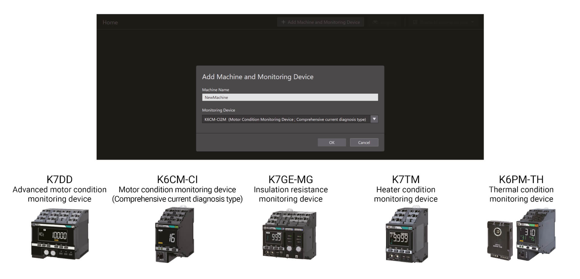
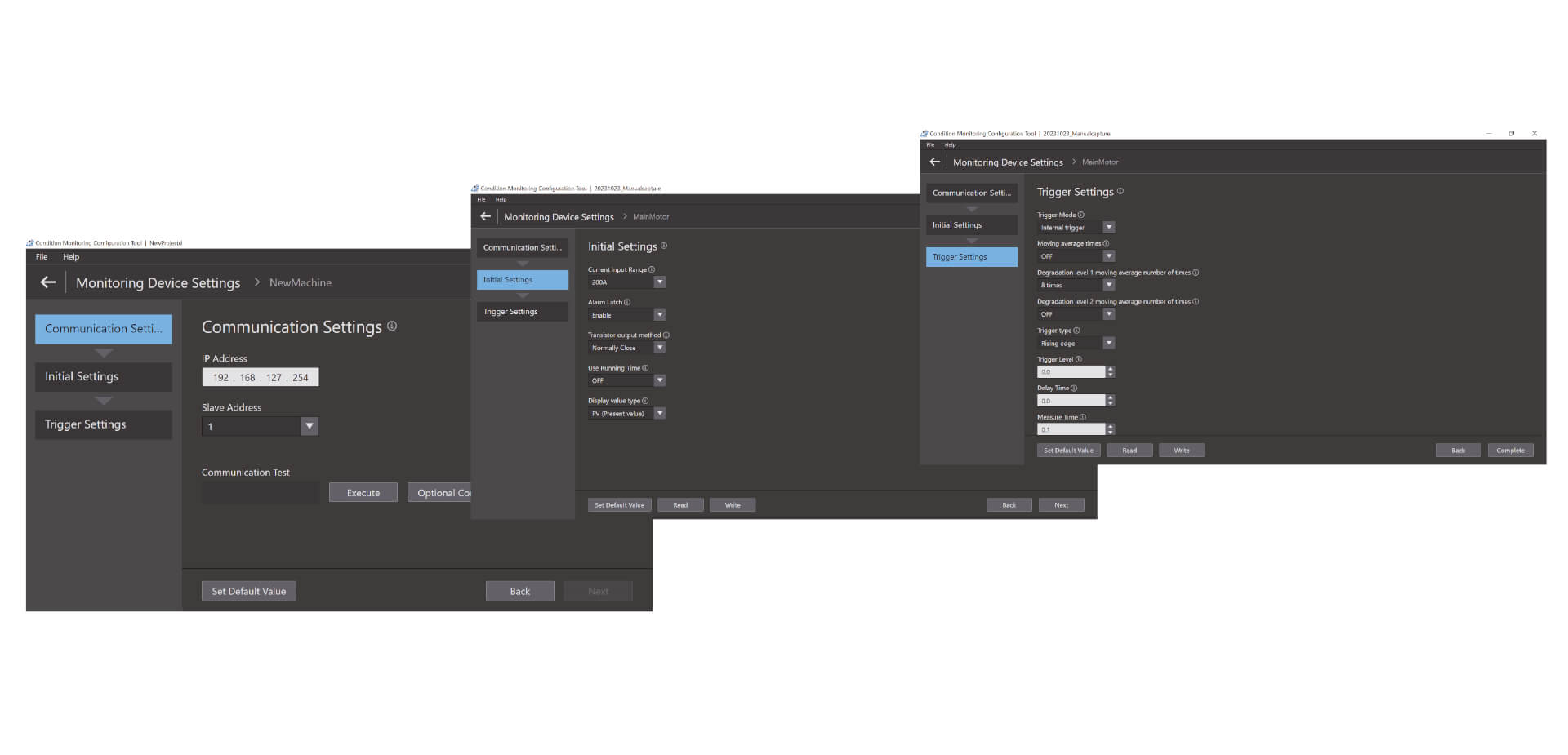
Une configuration facile en trois étapes
L'outil de configuration de surveillance de l'état permet la configuration par lots d'une large gamme de dispositifs de surveillance de l'état, tels que ceux pour la surveillance des moteurs, des températures, de l'isolation et des éléments chauffants. Il peut être utilisé sans compétences particulières, réduisant ainsi les besoins de formation. La configuration s'effectue en trois étapes seulement : configuration des communications, configuration initiale et configuration du déclencheur.*1 Grâce à son fonctionnement avancé, cet outil améliore également la productivité sur site.
Vidéos

-
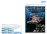
K6CM Motor Condition Monitoring Device
K6CM takes the burden of monitoring motors off maintenance engineers. Motors can be maintained in advance of failure due to deterioration. K6CM (comprehensive current diagnosis type) can consistently monitor motor conditions by observing the current waveform of the motor. Additionally, you can understand the motor's maintenance timing without depending on an engineer, because K6CM provides threshold value setting.
02:40
K6CM Motor Condition Monitoring Device
K6CM takes the burden of monitoring motors off maintenance engineers. Motors can be maintained in advance of failure due to deterioration. K6CM (comprehensive current diagnosis type) can consistently monitor motor conditions by observing the current waveform of the motor. Additionally, you can understand the motor's maintenance timing without depending on an engineer, because K6CM provides threshold value setting.
-

K6CM Demo Video
05:48
K6CM Demo Video
Solutions
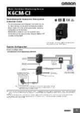
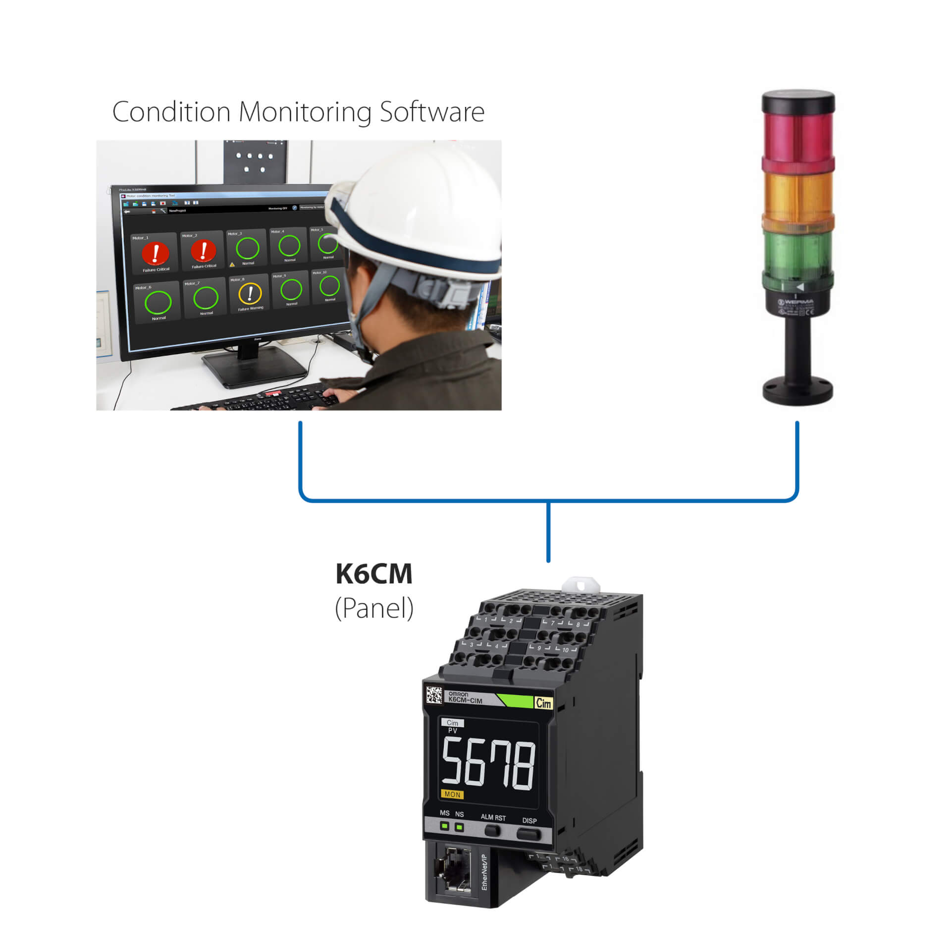
Installation autonome (sans API)
Avantages de cette solution simple :
- Surveiller l'état du moteur via la LED intégrée ou le logiciel de surveillance d'état
- Configurer les contrôleurs à l'aide du logiciel de contrôle d'état fourni avec l'appareil
- Interfacer le K6CM avec tout périphérique d'E/S externe (sortie num.)
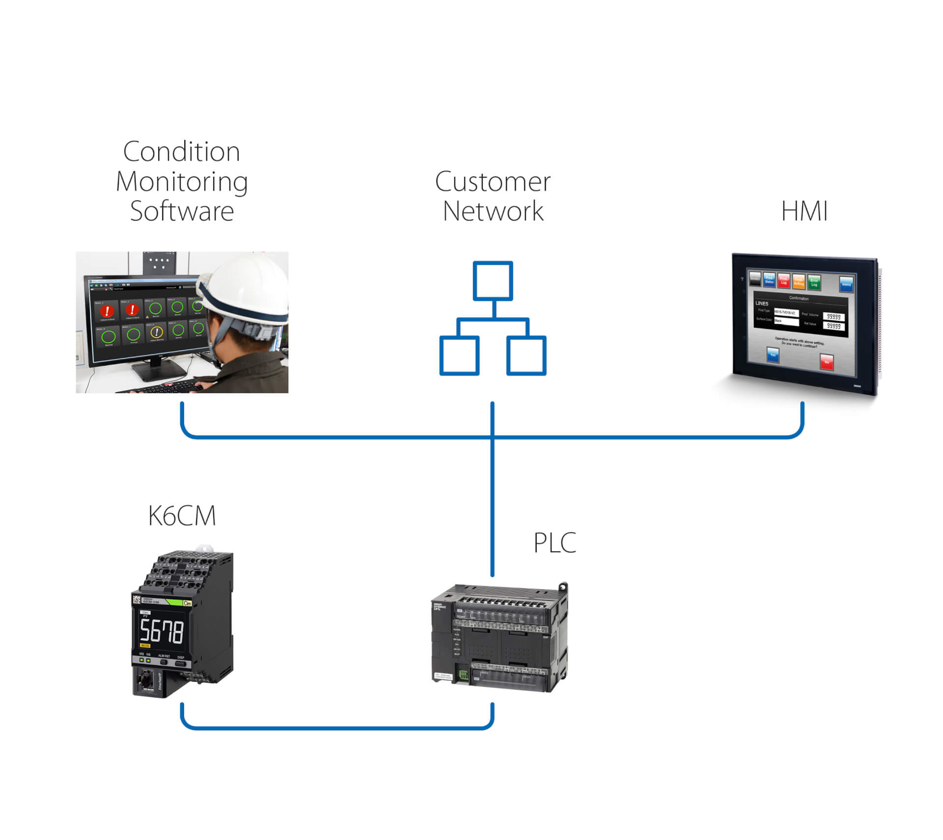
Installation autonome (avec API)
Cette solution permet, en plus de la solution précédente :
- De surveiller l'état du moteur jusqu'au logiciel de contrôle de condition, exécuté sur un PC connecté via une API
- De déclencher, via l'API, des actions suite à tout avertissement/toute alarme détecté(e) par le K6PM
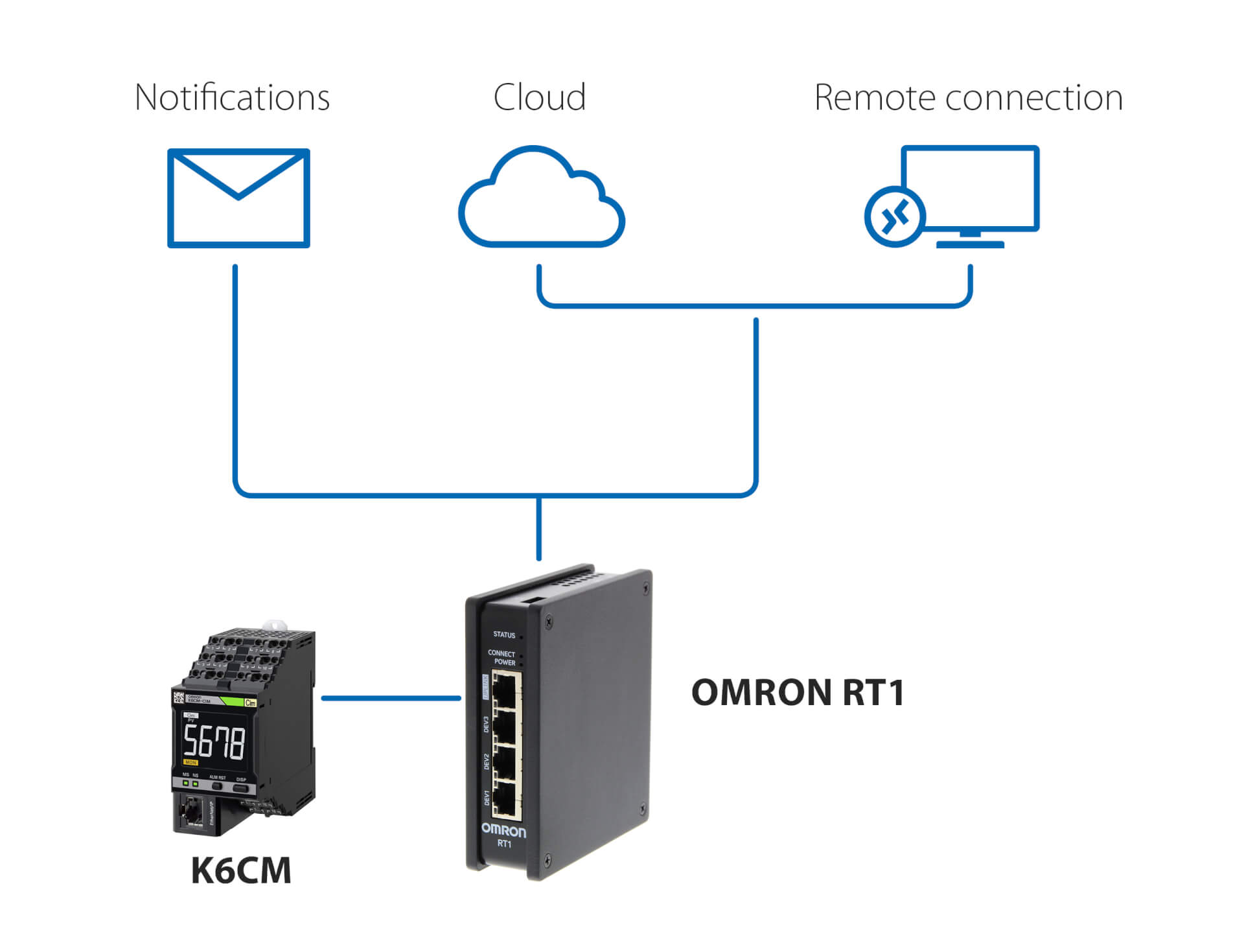
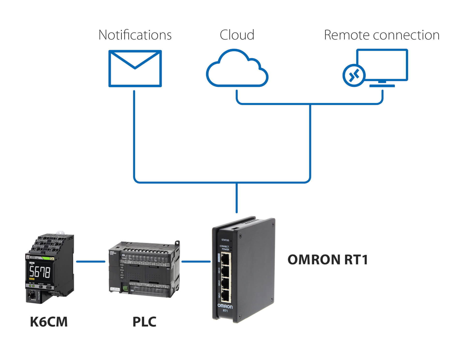
Notifications et surveillance à distance sans API
Avantages de cette solution utilisant OMRON RT1 comme passerelle :
- Notifications par e-mail/SMS en cas d'anomalies détectées par le K6CM
- Connexion sécurisée (gérée par la solution RT1) au Cloud, via une connexion LAN ou 4G
- Connexion sécurisée pour la surveillance à distance et la configuration du K6CM, à l'aide du logiciel de surveillance de condition fourni avec le contrôleur
Notifications et surveillance à distance avec API
Avantages de cette solution, utilisant n'importe quelle API et OMRON RT1 comme passerelle :
- Notifications par e-mail/SMS en cas d'anomalies détectées par le K6CM
- Connexion sécurisée (gérée par la solution RT1) au Cloud, via une connexion LAN ou 4G
- Connexion sécurisée pour la surveillance à distance et la configuration du K6CM, à l'aide du logiciel de surveillance de condition fourni avec le contrôleur
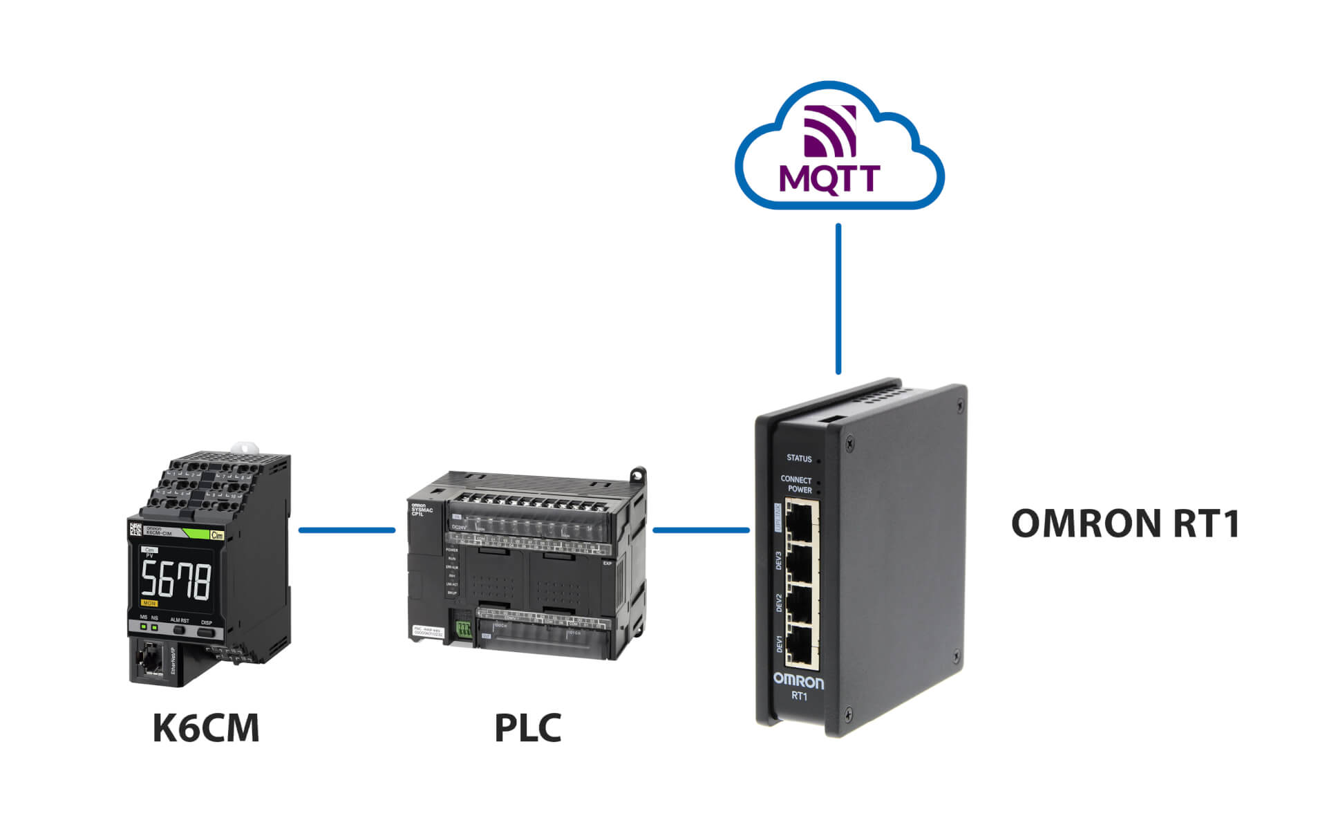
Connexion au serveur MQTT
Produits liés
-
Dispositif de surveillance de l'état du moteur : surveillance du courant
-
Dispositif de surveillance de l'état du moteur : surveillance de l'isolation
-
Surveillance d'état basée sur la thermographie
-
Dispositif de surveillance de condition : surveillance de l'isolation
Téléchargements